2.Instructions of usage
Based on GSM/4G communication frequency, support 1000 users, authorized users can remote control the your equipment that connect with the GSM, 3G, 4G Remote Controller (RTU5024) by free calling or SMS with app, and the control result will feedback to users by SMS, no distance limited.The device is widely used in access control systems, garage doors, swing doors, folding doors, parking systems, and other electronic equipment, the device will send notifications to users (via SMS) of the remote control results (such as the opening and closing status of doors).
3.Physical Layout
Due to the continuous improvement of the product, some content and illustrations in this manual may not be completely consistent with the product you actually received, please note.
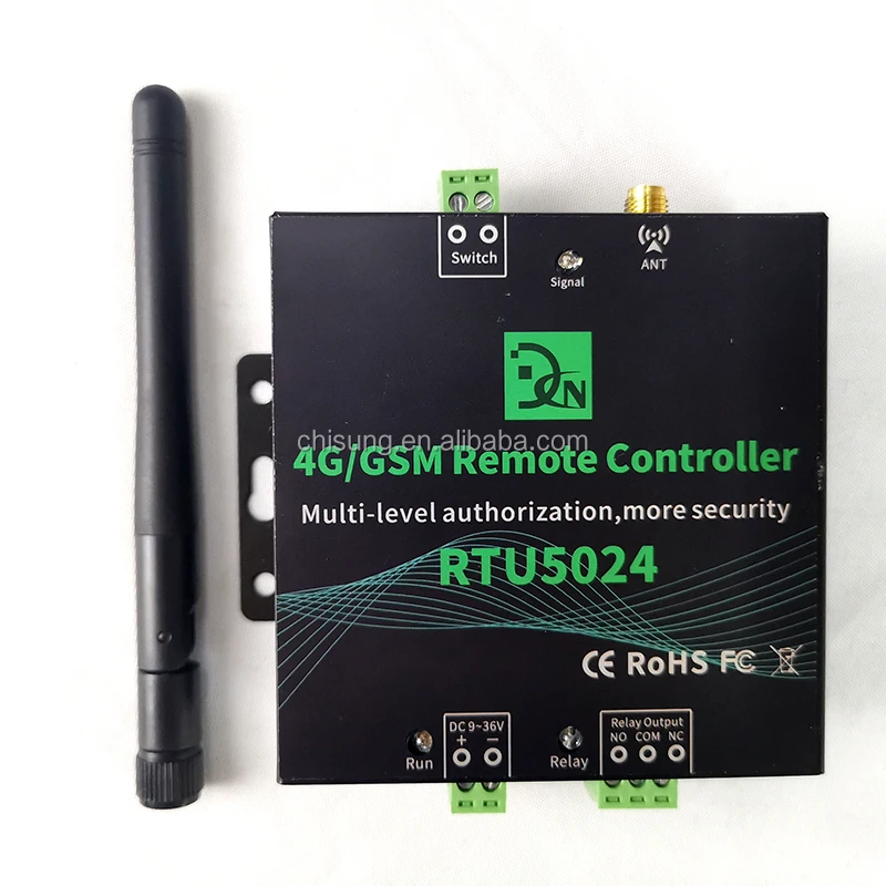
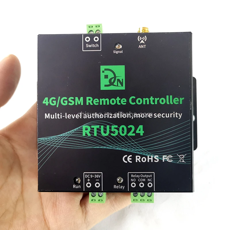
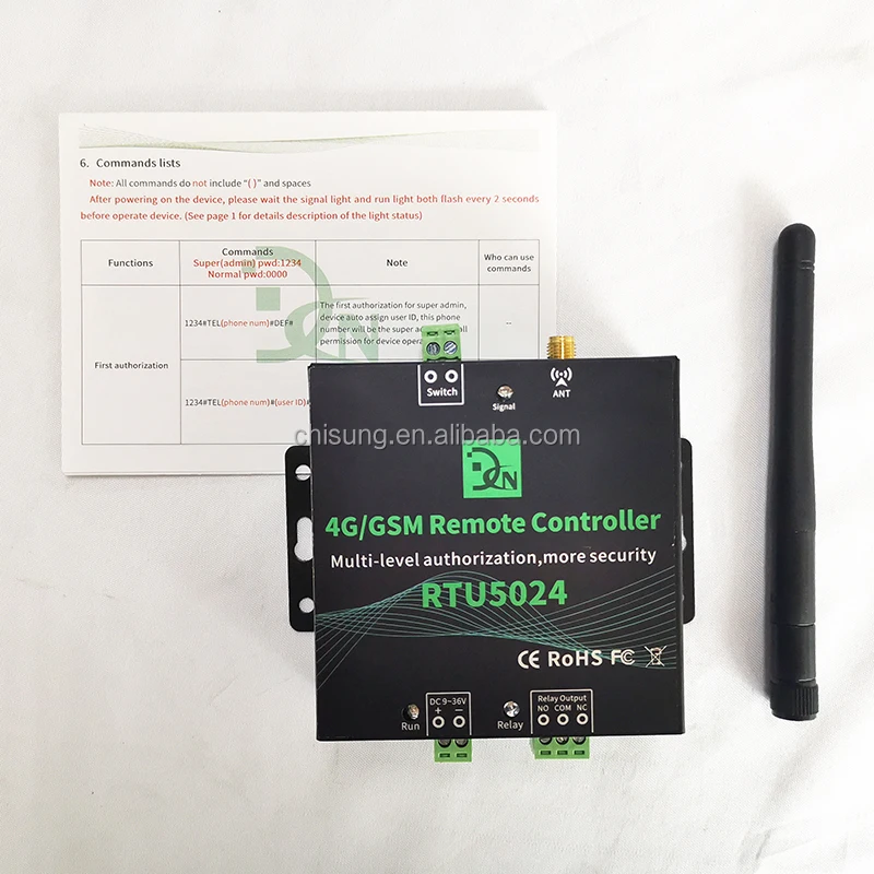
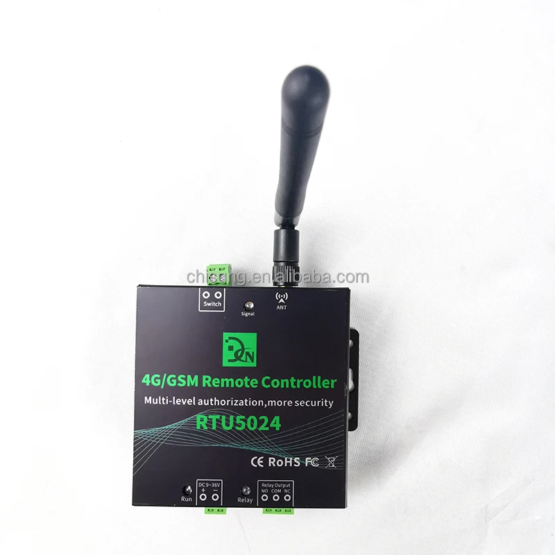
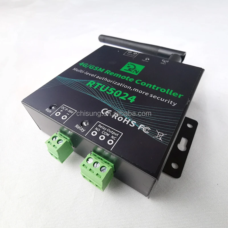
Port, light and button instruction
ANT | Antennas port |
Signal | Signal light: 1.Registering the network signal: flashes quickly, once per second 2.The network registration is successful: flashes quickly, flash every 2 seconds 3.Reset successfully; quick flash 4 times |
Run | Run light: 1.Device is loading SMS function: long light about 2 seconds 2.Loading and process SMS successfully: slowly flash, flash every 2 seconds 3.Reset successfully; quick flash 4 times |
Relay | Relay on: lightning; Relay off: light off |
Reset Button | Reset button: 1.The button is located in the groove on the back of the device (A tool is required to open the cover on the back of the device) 2.Press for 5 seconds to reset, it will delete all parameters before authorized. Reset successfully, the RUN light will flash 4 times quickly, then device will short power off and restart. 3.Quickly press the reset button 2 times, the run and signal light will enter a silent status, press the reset button 1 time, the light will return normal flash. 4.Quickly press 4 times to reboot device. |
Connect port
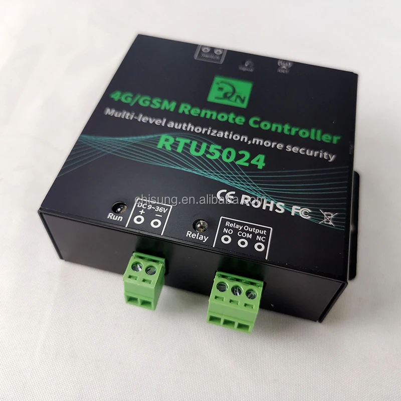
DC 9~36V | + | Power supply input, Positive wire. |
- | Power supply input, Negative wire. |
Relay Port | NO | Normally Open port. The relay is 5A/250VAC, 7A/125VAC, 20A/14V Connect to the switch of the electronic lock or device. |
COM | Common port. The relay is 5A/250VAC, 7A/125VAC, 20A/14V, 20A/5V. Connect to the switch of the electronic lock or device. |
NC | Normally Close port. The relay is 5A/250VAC, 7A/125VAC, 20A/14V, 20A/5V. Connect to the switch of the electronic lock or device. |
Switch | Dry contact, used to be connected with wired switch, like push button, it can active the relay. |
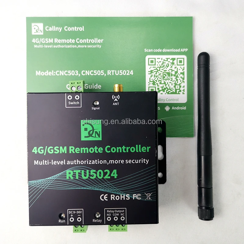
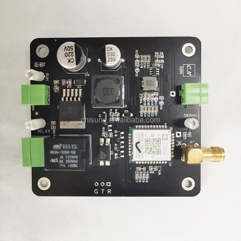
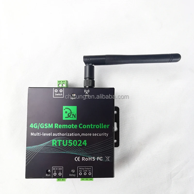
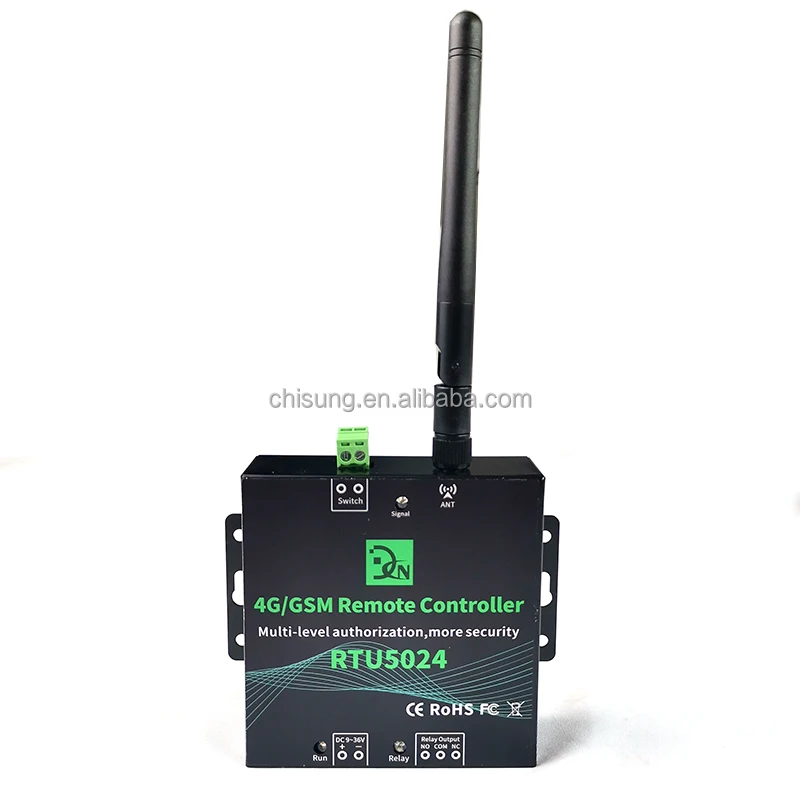
Product display
Installation
1.A nano SIM card support basic communication function for SMS and calling, close the PIN lock, install the SIM card into the slot. (SIM card slot located in the groove on the back of the device)
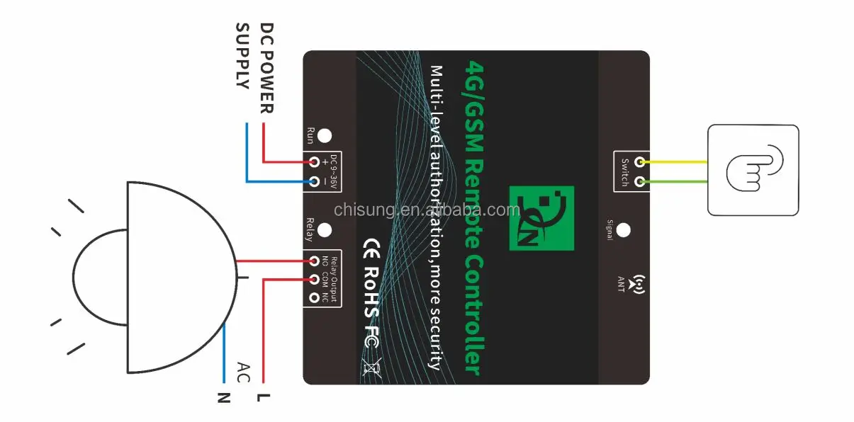
2.Connecting diagram. (As follow)
3.After powering on the device, please wait for the signal light and the run light flash at the same time (every 2 seconds), and then begin to operate the device. (See page 1 for details description of the light status)
4.Follow the commands list to operate. (As follow)
5.After the first authorize successfully, follow the commands list to do other settings.
Connecting diagram
The wiring diagram is for reference only, and the wiring diagrams of different models are slightly different.
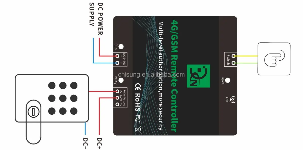
The wiring diagram is for reference only, and the wiring diagrams of different models are slightly different.
